Shandong Popweld Automatic Equipment Co., Ltd.

Leave Your Message
Choosing a China top Swing Weld Carriage supplier requires more than comparing prices and catalog photographs. Welding workshops need stable travel, accurate torch positioning, and dependable operation during long production runs. A suitable carriage should move smoothly across rails, maintain consistent speed, and support practical adjustments for different joint designs. Small details matter. A loose clamp or uneven wheel can affect weld quality.
Experienced buyers usually examine engineering capability, manufacturing records, and after-sales support. They may request videos of factory testing, load information, control-system details, and samples from similar welding applications. Reliable suppliers can explain motor selection, travel accuracy, welding compatibility, and maintenance procedures clearly. They should also provide inspection reports and realistic delivery schedules. Promises alone are not enough.
However, supplier evaluation is rarely perfect. A polished factory tour cannot replace operating data from real workshops. Product performance may change under heat, dust, vibration, or heavier workloads. This point deserves attention. Buyers should test the Swing Weld Carriage with their own torch, workpiece dimensions, and production rhythm whenever possible. Communication quality also reveals much. Does the supplier answer technical questions directly? Can engineers respond after installation? A strong partnership depends on honest limits, documented support, and continuous improvement. The “top” supplier may not be the cheapest or largest. It is often the one that delivers consistent performance, explains weaknesses openly, and helps customers reduce welding problems over time. Reliability grows through evidence, not attractive wording.
China Top Swing Weld Carriage Supplier?
What Is a Swing Weld Carriage?
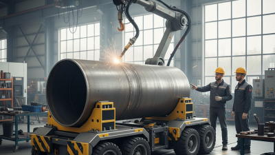
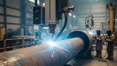
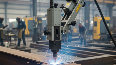
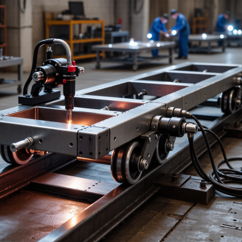
A swing weld carriage is a mobile welding device that travels along a planned path. It supports a welding torch and maintains a steady travel speed. The swing mechanism moves the torch from side to side. This motion creates a wider weld bead than straight travel alone. It is useful for tanks, pipes, steel frames, and long seams. Operators can adjust speed, swing width, dwell time, and travel direction. These settings help match the joint design and welding process.
In practical use, the carriage reduces hand movement and improves consistency. It also helps limit uneven bead width and operator fatigue. However, it cannot correct poor joint preparation. Rust, gaps, incorrect alignment, or unstable power can still weaken the weld. I have found that a simple trial weld often reveals problems earlier than complicated adjustments. A carriage may look efficient, but setup quality still matters.
Tips: Check the rail or guide before welding. Keep the torch angle stable. Test the swing pattern on scrap metal first. Measure the bead after cooling. If the carriage drifts, inspect wheels, cables, and surface cleanliness. Do not rely on speed settings alone. Real workshop conditions can change during production.
| Data Dimension | Typical Specification or Range | What It Means | Practical Selection Considerations |
|---|---|---|---|
| Definition | Motorized welding travel carriage with torch oscillation | A swing weld carriage moves a welding torch along a joint while swinging it from side to side across the weld path. | It is used to maintain a consistent travel speed and create a wider, more uniform weld bead than a straight-line carriage. |
| Primary Welding Processes | MIG/MAG, FCAW, TIG, and submerged arc welding | The carriage is a motion system; the welding process depends on the torch, power source, wire feeder, shielding gas, and consumables. | Confirm torch mounting, cable clearance, grounding arrangements, and compatibility with the selected welding process. |
| Travel Speed | Commonly adjustable from approximately 0.1 to 1.5 m/min | Travel speed controls how quickly the carriage moves along the joint. | The correct speed depends on welding current, voltage, wire-feed speed, material thickness, joint design, and required heat input. The actual usable range varies by design. |
| Oscillation Width | Typically adjustable from approximately 0 to 30 mm | Oscillation width is the total side-to-side movement of the torch across the joint. | A wider oscillation can cover broader joints, but excessive width may reduce sidewall fusion or produce uneven penetration. |
| Oscillation Frequency | Typically adjustable from approximately 0 to 3 Hz | Frequency determines how many complete swing cycles the torch makes per second. | Higher frequency generally creates a more closely distributed bead pattern, while lower frequency increases dwell time at each side of the joint. |
| Oscillation Patterns | Straight, triangular, trapezoidal, and stepped patterns | The pattern defines how the torch accelerates, decelerates, and dwells during each oscillation cycle. | Triangular and trapezoidal patterns are often used for sidewall coverage; the best pattern depends on joint geometry and welding procedure requirements. |
| Dwell-Time Control | Independent left and right dwell adjustment on advanced controllers | Dwell time is the period the torch remains near either edge of the oscillation path. | Adjustable dwell can improve sidewall fusion and help compensate for different heat-loss conditions on each side of a joint. |
| Rail or Track System | Flexible rail, rigid rail, or magnetic track | The track guides the carriage and determines how accurately it follows the weld seam. | Flexible rails suit curved surfaces, rigid rails provide better geometric stability, and magnetic systems are useful on suitable ferromagnetic workpieces. |
| Workpiece Orientation | Flat, horizontal, vertical, and selected circumferential applications | The carriage can be configured for different welding positions when its drive, support, and retention systems are suitable. | For vertical or overhead work, verify anti-drop protection, traction, rail attachment, and the permissible operating angle before use. |
| Drive Mechanism | Geared electric motor with traction wheels or rack-and-pinion drive | The drive converts motor rotation into controlled linear travel along the guide system. | Gear reduction, wheel material, rail condition, and load distribution affect speed stability and resistance to slipping. |
| Torch Load | Usually designed for one torch and its cable package | The torch holder must support the torch, contact tip area, hose package, and any oscillation force without excessive vibration. | Check the permitted torch weight, holder adjustment range, cable routing, and clearance from the workpiece and rail. |
| Power Supply | Commonly low-voltage DC input through a dedicated controller | The carriage motor and control system normally operate separately from the welding power circuit. | Verify input voltage, connector type, duty cycle, grounding, and protection against dust, moisture, and welding spatter. |
| Control Functions | Travel speed, oscillation width, frequency, pattern, and dwell settings | These parameters allow the carriage motion to be matched with the welding procedure. | Digital displays, parameter memory, remote controls, and synchronized start/stop functions can improve repeatability in production work. |
| Welding Joint Applications | Fillet, lap, butt, corner, and longitudinal seams | The carriage can support consistent torch travel on long or repetitive seams. | Use a suitable guide method and torch angle for each joint. Oscillation does not replace correct joint preparation or welding procedure qualification. |
| Productivity Benefit | More consistent travel than manual torch movement | Mechanized travel reduces variation in speed and torch motion over repetitive welds. | Productivity gains depend on setup time, joint length, welding parameters, repositioning requirements, and inspection criteria. |
| Key Quality Factors | Stable speed, accurate alignment, controlled oscillation, and consistent torch distance | These factors directly influence bead width, penetration, sidewall fusion, and appearance. | Inspect rail alignment, wheel traction, torch positioning, cable drag, and parameter settings before starting production welding. |
| Recommended Maintenance | Clean rails, inspect wheels, check fasteners, and protect cables | Contamination and mechanical looseness can cause vibration, speed fluctuation, or carriage drift. | Remove spatter regularly, inspect drive components, check electrical connections, and follow the equipment service schedule. |
| Safety Requirements | Emergency stop, secure mounting, cable management, and electrical protection | A moving welding carriage combines mechanical motion, heat, ultraviolet radiation, fumes, and electrical hazards. | Use appropriate personal protective equipment, ventilation, fall prevention where required, and a risk assessment suitable for the welding position. |